|
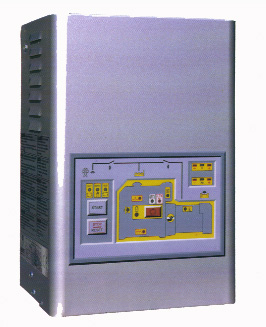
QUADRO AUTOMATICO
Q 930
Il quadro elettrico
Q 930 per il controllo e l’avviamento automatico del gruppo
elettrogeno consente l’alimentazione di utenze elettriche entro pochi
secondi (10 – 15) dal segnale di mancanza di tensione di rete,
FUNZIONAMENTO IN
AUTOMATICO
Al segnale di mancanza tensione rete e
trascorso il ritardo avviamento di 10 sec., la centralina comanda
l’apertura del teleruttore rete ed inizia l’avviamento. Per facilitare
l’avviamento viene eseguita una successione di 4 tentativi di
avviamento, dopo il quarto tentativo, se il motore non si è avviato la
centralina blocca il ciclo di avviamento per evitare di scaricare la
batteria. A motore in moto dopo il ritardo inserimento generatore
all’utenza di 7 sec., si ha la chiusura del teleruttore generatore. Al
ritorno della tensione rete e trascorso il ritardo di stabilizzazione
rete di 40 sec. la centralina comanda l’apertura del teleruttore
generatore e con un ritardo di 1,5 sec. la chiusura del teleruttore
rete. L’arresto del motore avviene dopo 120 sec. per consentirne il
raffreddamento. Il gruppo generatore durante il suo funzionamento è
protetto da eventuali anomalie con l’arresto del motore per
insufficienza pressione olio, rotture cinghie o alternatore carica
batteria, sovrafrequenza.
FUNZIONAMENTO
MANUALE
L’avviamento e l’arresto vengono gestiti
tramite gli appositi pulsanti:
START :
avvia il motore,
comanda l’apertura del contattore rete e la chiusura del contattore
generatore, mantiene il motore in moto anche a rete presente.
STOP :
arresta il motore, comanda l’apertura del contattore generatore e la
chiusura del contattore rete (a rete presente) e 15 secondi dopo il suo
rilascio ripristina il funzionamento automatico.
RESET :
ripristina le protezioni da anomalie.
IL QUADRO E’
PREDISPOSTO PER COMANDI A DISTANZA :
avviamento, arresto,
prova di test, arresto di emergenza e blocco.
COMPONENTI QUADRO :
-scheda elettronica;
-indicatori di
frequenza e tensione;
-contattori
RETE/GRUPPO;
-carica batteria
automatico controllato in corrente ed in tensione.
SEGNALAZIONI OTTICHE
: per
presenza tensione rete, utenza alimentata dalla rete, utenza alimentata
dal generatore, motore in moto, anomalia generatore, arresto per
sovrafrequenza, arresto per anomalie motore causate da una bassa
pressione olio, rottura cinghia o alternatore carica batteria, blocco
generatore, mancato avviamento, carica batteria in funzione, delle
funzioni di avviamento in automatico, manuale o autotest settimanale.
MORSETTIERA PER
CIRCUITI AUSILIARI DI POTENZA
Non sono compresi nella fornitura i cavi di
collegamento tra gruppo e quadro manuale.
|
|
Q 930
AUTOMATIC TRANSFER PANEL
With a
generating set wired to the Q 930 control panel, power can be
switched in automatically to electrical services within just a few
seconds (10 – 15) after activation of the signal indicating a cut in the
mains supply.
OPERATION IN AUTOMATIC MODE
Loss of
mains power (indicated by a voltmetering relay installed inside the
panel) will cause a contact to close, and, following a delay of 10
seconds, the control circuitry will pilot the mains isolating switch to
open and begin the starting sequence. The system is programmated to
effect a succesion of 4 start attempts; if the engine has still not
started after the fourth attempt, the sequence will be suspended to
avoid running down the battery.With the engine running, a 7 second delay
is allowed to lapse before power is connected to the service by closing
the generator output switch. Once mains power has been restored, there
will be a delay of 40 seconds to verify stabilization, before opening
the generator output switch and, after a further delay of 1,5 seconds,
closing the isolating switch. The engine will continue running for 120
seconds before shutting off to allow cooling. When running, the
generating set is protected against faulty operation of malfunction by
safety system which will shut off the engine in the event of low oil
pressure, overfrequency, fan belt failure or breakdown of the alternator
occuring.
OPERATION IN MANUAL MODE
The
starting and the shut-off of the genset are piloted by the apposite
buttons.
START :
it
starts the engine, pilots the mains isolating switch to open and the
generator output switch to close, keeps the engine running also when
there is the mains supply.
STOP :
it stops
the engine, pilots the generator output switch to open and the mains
isolating switch to close (when there is the mains supply) and restores
the automatic mode after 15 seconds.
RESET :
it
restores the protection against faulty operation or malfunction.
REMOTE
CONTROL :
the
panel is wired to allow remote control on start, test and off function.
INSTRUMENTATION :
-control
unit;
-frequency and voltage control;
-GENSET/MAINS SUPPLY contactors;
-automatic battery charger controlled in current and tension.
VISUAL
INDICATORS :
mains
healty, service operating off mains, service operating off generator,
engine running, generator fault alarm, shut-off in the event of
generator overfrequency , shut-off in the event of low engine oil
pressure, belt failure or breakdown of the alternator occuring, failed
start, battery charger in function, automatic or manual mode and weekly
self-test.
TERMINALS FOR AUXILIARY AND POWER CIRCUIT CONNECTION
The connection cables between the genset and the manual panel are not
included in the supplying.
|